Ventilation in buildings
-Simulation Methodology & Parameters
Validated Software: We provide full substantiation for CFD software validity, ensuring compliance with international standards and best practices.
- Standard-Compliant Analysis: Every study is executed following global industry benchmarks, clearly defining:
- Physical Modeling: Accurate representation of real-world physics.
- Computational Domain: Optimized domain size, geometry, and boundary conditions.
- High-Resolution Gridding: Precision control over grid resolution and expansion ratios.
- Numerical Accuracy:Rigorous numerical approximations and solution verification.
- Regulatory Liaison: We facilitate in-principle agreement from the Building Authority (BA) on methodologies prior to formal submission.
CFD Simulation in Building Design
We utilize advanced Computational Fluid Dynamics (CFD) to optimize natural ventilation. Figure 1 below illustrates the airflow patterns through building louvres. Figure 2 shows a contour map displaying the velocity distribution as air passes through the louvres.
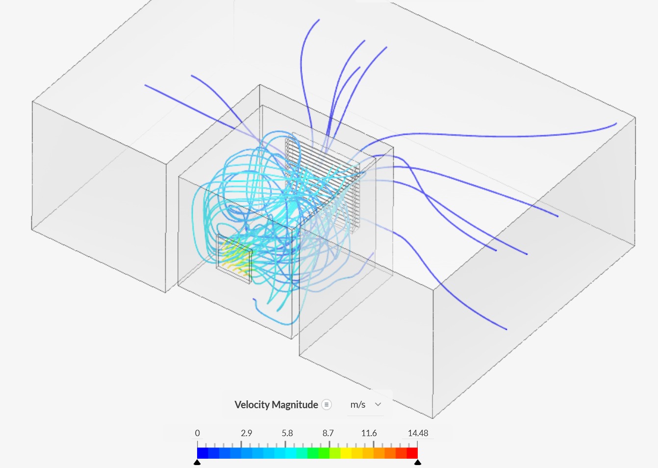
Figure 1 Airflow pattern of Ventilation through louvres in buildings.
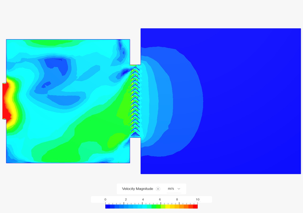
Figure 2 Velocity distribution of air flow through louvres.
Physical Modeling – Wind Tunnel Test
Wind tunnel is located in Hong Kong.
Precision, accurate, and regular calibrated instruments includes hot-wire anemometer, omni-directional sensors, cobra probe, electronic pressure scanners, force gauge, together with automatic sampling software, which can measure wind speed, wind direction, wind pressure, turbulence intensities…etc.
Wind load measurement with atmospheric boundary layer simulation
LASER-Aided Flow Visualization
Apart from flow measurement, LASER-Aided Flow Visualisation provide another insight of fluid flow. The fog is generated by fog machine and injected into wind tunnel for tracing the flow. A laser plane is used for illuminating the fog.
Smoke exhausted from chimney
Flow around chimney
Should you have any questions, please contact us at 3586 1826.
